Designing a Multirotor Drone in Onshape: My Journey into Aerospace Systems and CAD Engineering
🛫 Introduction
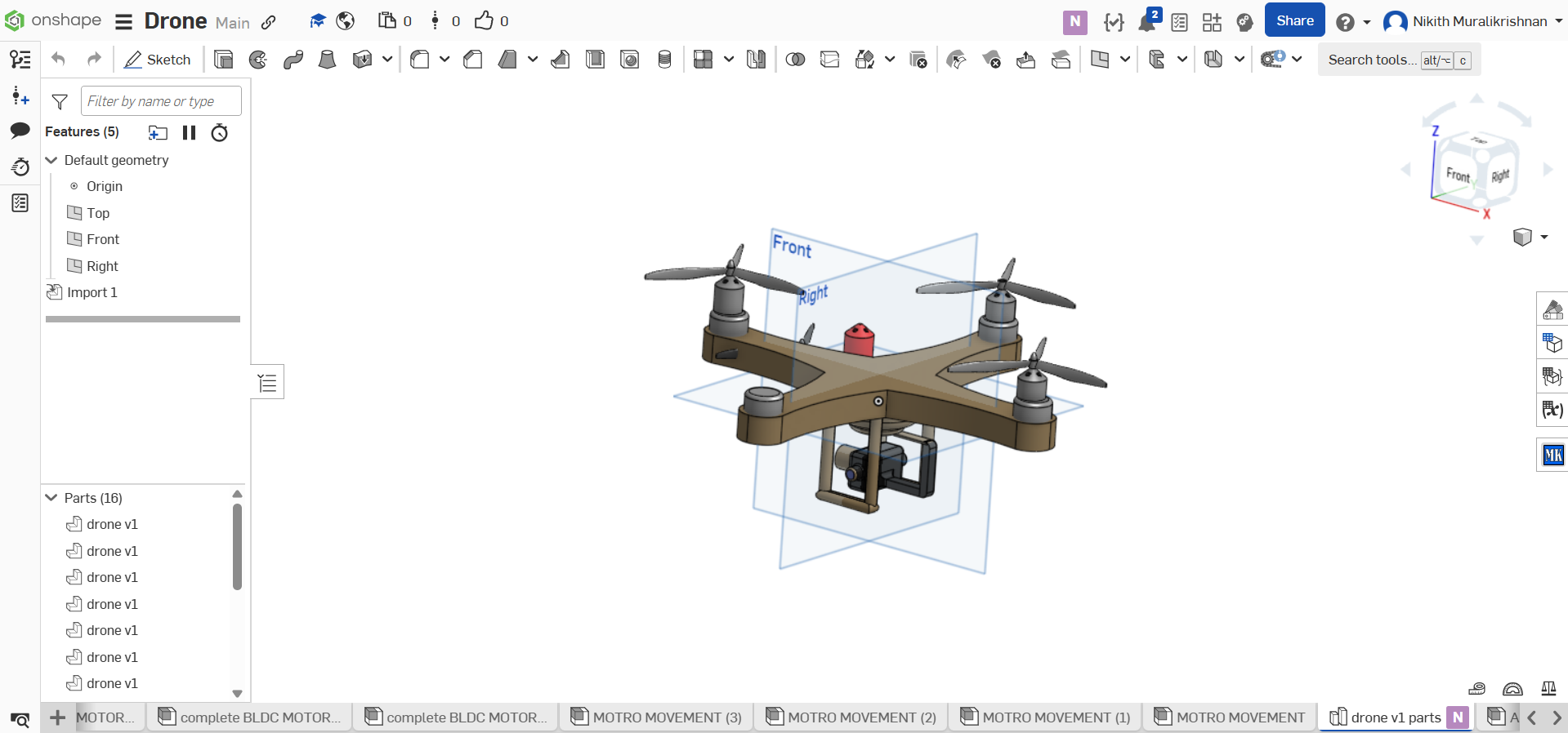
- This project involved designing a multirotor drone using Onshape, a professional-grade cloud CAD platform.
- The objective was to explore the mechanical structure and spatial layout of aerial vehicles while developing skills applicable to aerospace systems design.
- My passion lies in the intersection of aerospace engineering and computer science. This project is the foundation for more complex work involving control systems, autonomy, and embedded programming.
🎯 Project Goals and Engineering Purpose
- Primary Goal: Create a modular, realistic drone design using engineering CAD principles.
- Long-Term Vision: Prepare to integrate hardware (e.g., Arduino, sensors) and software (flight logic, control algorithms) to prototype an autonomous flight system.
- Why Aerospace: I’m drawn to the challenge of designing systems that must operate with high precision, stability, and real-time processing—characteristics found in both aerospace hardware and software.
- Future innovations: This design phase lays the groundwork for:
- Embedded systems programming (e.g., Arduino flight control)
- Sensor data processing (IMU, GPS)
- Autonomous navigation and software-based stabilization
- Possible use of ROS (Robot Operating System) in the future
🔧 Design Process Overview
🔍 a. Research and System Planning
- Evaluated different multirotor types: quadcopters, hexacopters, and octocopters.
- Chose a quadrotor design for its balance between simplicity and functionality.
- Referenced real drone specifications (motor size, thrust-to-weight ratio, ESC layouts) to make the model physically plausible.
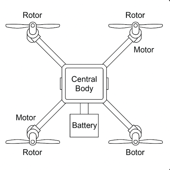
🧱 b. Base Frame Construction
- Created a symmetric cross-layout with parametric arm spacing to maintain center of gravity.
- Designed the central hub to support a control board, power distribution, and frame rigidity.
- Considered center of mass, moment of inertia, and air clearance during sketch phase.
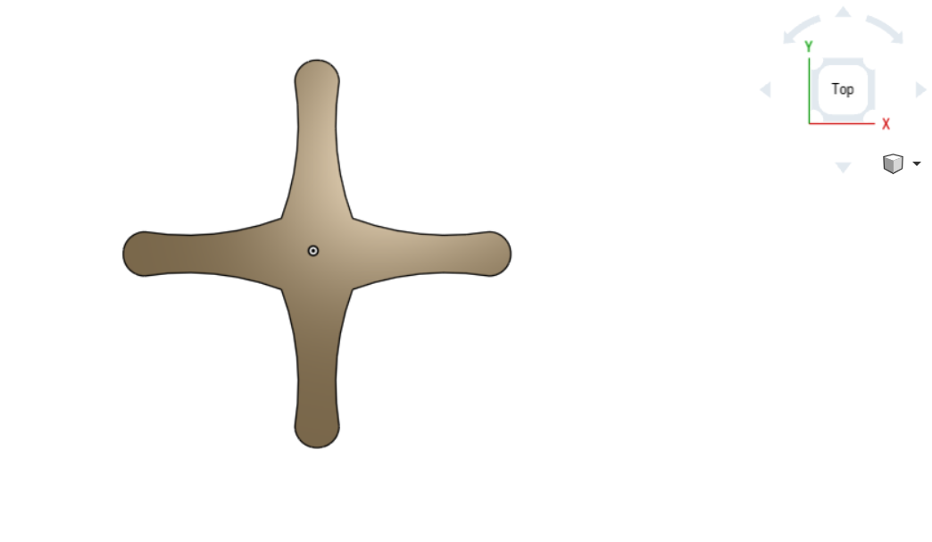
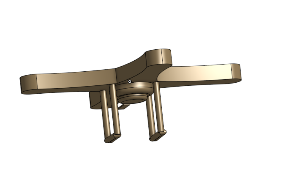 This is a model of the landing gear being used for the drone, attached to the base
⚙️ c. Component Modeling
- Modeled individual components:
- Rotor mounts and motor housings
- Battery bay sized for standard LiPo cells
- ESC trays and wiring guides
- Created full subassemblies to support testing different layouts
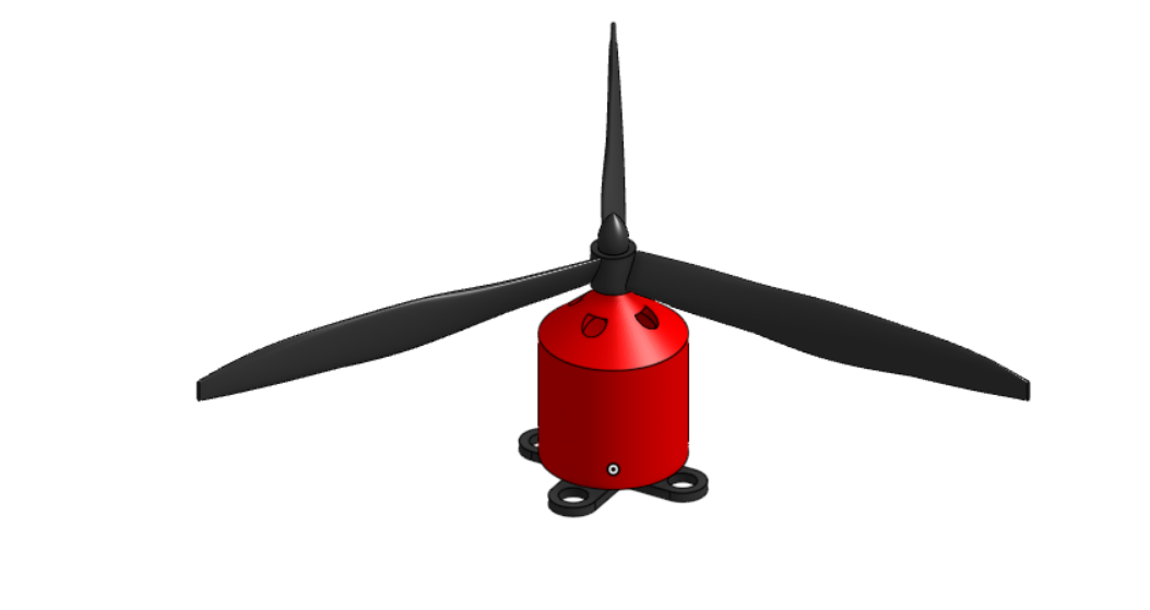 3d design for one of the four individual rotors for the multirotor drone
—
3d design for one of the four individual rotors for the multirotor drone
—
🧠 d. Systems Thinking & CS Integration
- Modeled with a modular mindset, similar to software architecture:
- Each component (motor, arm, ESC, controller) is treated like a function or class in a program.
- Assemblies mirror how we compartmentalize subsystems in CS (e.g., object-oriented structure).
- Future CS applications:
- Arduino-based flight controller with PID stabilization
- Python or C++ code for sensor integration
- Real-time telemetry and debugging via serial/UART communication
- Simulation of flight using MATLAB Simulink
🖼️ Final Model Summary
- Fully assembled drone CAD in Onshape, ready for 3D printing and prototyping.
- Includes:
- Rotor system and arm mounts
- Battery housing with wire guides
- Control board bay and frame spacers
 Bottom view, shows the landing gear
 Front view of the drone
 Side view, showcases the symmetry of the drone
 Top view, shows more of the rotors used for the drone
—
Top view, shows more of the rotors used for the drone
—
🛠️ Engineering Challenges & Solutions
- Precision Alignment: Ensured motor symmetry using construction planes and constraints.
- Wire Routing: Modeled internal channels for ESC and battery leads to preserve aerodynamics.
- Part Management: Used named assemblies and version control in Onshape to isolate design iterations.
📘 Key Takeaways
- Strengthened CAD workflow using design trees, constraints, and assemblies.
- Applied systems engineering concepts to design interconnected parts.
- Gained practical insight into how CS logic principles (modularity, abstraction, scalability) apply in physical engineering.
🧪 Next Steps: From CAD to Flight
- 3D print the full frame using PETG or carbon-fiber-infused filament for rigidity.
- Integrate Arduino Nano or STM32 for flight control, using MPU-6050 for IMU data.
- Develop software to handle stabilization, motor PWM control, and sensor fusion.
- Explore GPS integration and possibly implement waypoint-based autonomous flight.
🔗 Project Link & Visual Resources
🚀 Final Reflection
- This project represents my first step toward building real-world aerospace systems.
- By combining CAD design, physical prototyping, and CS principles, I’m preparing to build complex embedded systems with real-world applications.
- I look forward to using this foundation in my CS coursework next year, especially in projects involving hardware interaction, robotics, and control theory.
🧠 If you’re interested in aerospace systems, hardware programming, or robotics—let’s connect!